SUBJECT: Hatch Remote Mounting Distance Calculator
To achieve optimal performance when remote mounting Hatch LED drivers.
The Remote Mounting Distance Calculator provided by Hatch Lighting Inc. is a tool that can be used to achieve optimal performance and to account for losses due to extending the output leads of an LED module/fixture driver to a remotely-mounted Hatch LED driver.
TOOL DESCRIPTION
To use the tool, the user must supply the information outlined in the following procedure.
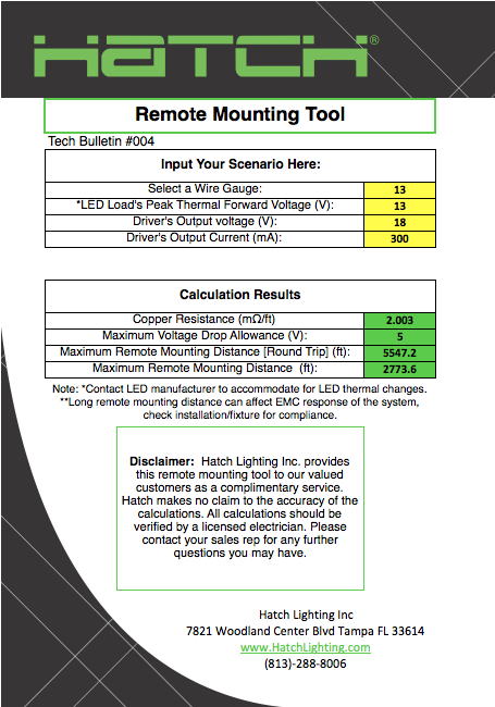
1. Select a wire gauge:
The resistance per foot of copper wire results in a voltage drop that affects the amount of power that gets delivered to the LED load. The resistance per foot is proportional to the wire gage. Therefore it is critical to pick the correct wire gauge for the application. The remote mounting tool is pre-configured with a wide selection of wire gauges.
2. Specify the peak thermal forward voltage of the LED load:
The forward voltage of an LED load shifts with temperature. Please refer to the LED module manufacturer specifications for this information.
3. Specify maximum driver output voltage:
The value selected should be below the output voltage limit of the LED driver. Hatch LED drivers are equipped with an overvoltage circuitry that limits the output current to a minimal value when the output voltage detected is above the limit of the driver. This is a protection circuit provided in Hatch drivers to protect the driver itself and the LED load from damage. In order to avoid triggering the overvoltage circuitry, the maximum output voltage of the driver used in the calculator should be below the output voltage limit of the driver.
4. Specify the output current of the driver:
Specify the DC driving current of the driver.
EXAMPLE
Scenario: Driving a 26V forward voltage LED load @ 1050mA using Hatch’s adjustable output current LED driver: XTC34-1050P-UNV-I with a 1.00 Key.
Steps:
1. Select the wire gauge:
For this example, we are specifying the wire gauge to be 24AWG.
2. Specify the peak thermal forward voltage of the LED load:
Although the forward voltage of the LED load is 26V, the manufacturer specifies the peak thermal forward voltage to be 28V. Therefore the peak thermal forward voltage of the LED load is set at 28V in the calculator.
3. Specify the output voltage of the driver:
Hatch specifies the output voltage limit to be 32V. The optimal output voltage should be 2V below the output limit in order to avoid triggering the overvoltage protection circuit. Therefore the output voltage of the driver is set at 30V in the calculator.
4. Specify the output current of the driver:
In this example, the XTC34-1050P-UNV-I with a 1.00 key is set at 1050mA.
Results:
The remote mounting tool suggests that the LED load and driver can be separated by a maximum distance of 24.7ft for this specific application.
CONCLUSION
The remote mounting tool is a spreadsheet-based calculator that can provide assistance to system designers when trying to determine acceptable remote mounting distances for Hatch LED drivers when separated from the LED load. The tool permits the designer to conduct scenarios to determine the maximum allowable distance based on wire gauge, maximum safe driver output voltage, maximum LED load voltage and LED load current.
The model does not factor in parasitic capacitances, series inductances or take into account stranded vs. solid wires. Also, the system designer should be aware that long remote mounting distance can affect the EMC response of the system. Hatch recommends that the distance between the LED load and the driver should always be kept to a minimum- typically less than 100 feet.
Click Remote Mounting Tool_004 to download the calculator
Click App notes- Remote Mounting to download the full application notes about the calculator